Quadcopter
I made a quadcopter…
While studying at UCSD on a study abroad program I took the class CS176E which was to design, build and program a small quadcopter. The quadcopter was to be made of a single PCB and the major components had been selected for us by the professor. This was in large part due to the time constraints we had for the class, we had only 10 weeks to design the PCB, validate and order the boards, have them ship from China, us to assemble and test them as well as programming the quadcopter and remotes in order to control them. The project was carried out in pairs and I got extremely lucky to work with Max who though was in his first year at UCSD was and continues to be extremely gifted and hard working. None of what we achieved would have been possible without him.
I will split this project page up broadly into the sections of work and briefly outline the work we completed. I will also be writing some blog posts going back over particular issues and challenges we faced and how we overcame them (as best I can remember) these will be linked here as well when I can figure out how to do that properly.
Goals
The goal of the project was to produce a single-PCB quadcopter that we could fly under control, including the design of the PCB all the way through the control software to communicate with and control it.
PCB Design
First of all we needed to learn how to design PCBs. I had never touched any PCB design software and had relatively little electronic engineering background but we didn’t have a lot of time so we started off with designing individual part footprints and connections. This we did from the design sheets using Eagle as the editor. Inevitably we had several issues with our first drafts of parts, usually these were dimensional issues that were easily resolved.
Some examples of non obvious constraints were that the IMU (Inertial Measurement Unit) needed to have several layers of keepout beneath it to make sure that no metal was placed below the chip as this would interfere with its operation.
Similarly the antenna was selected for us as we were not going to delve into antenna design.
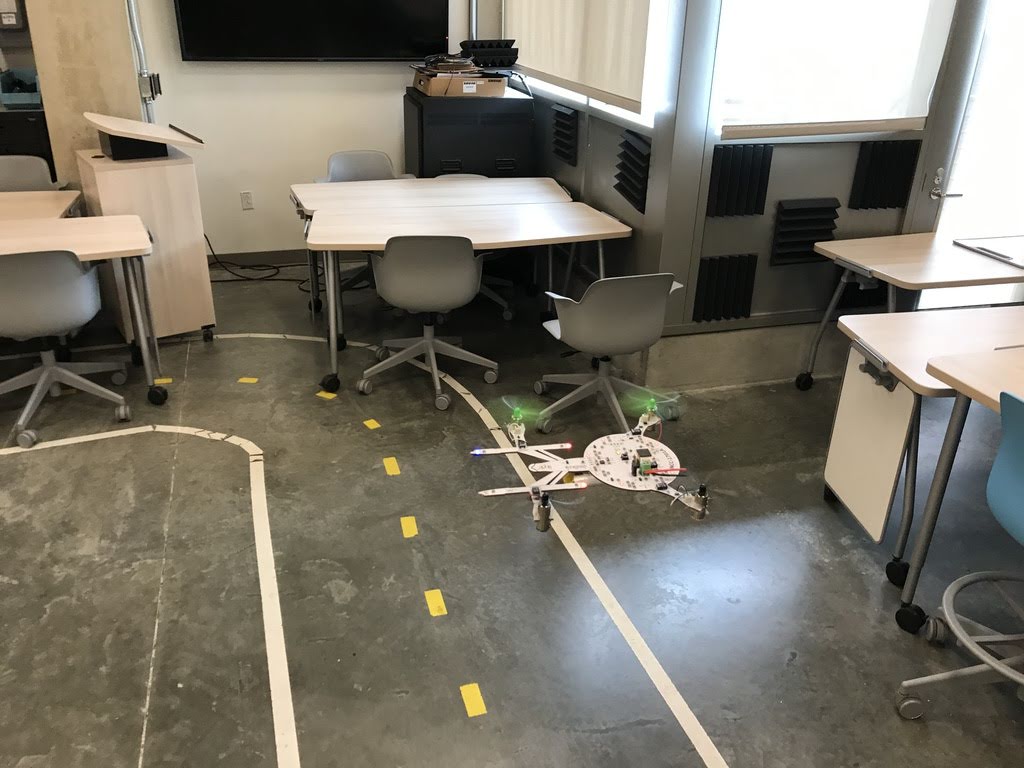
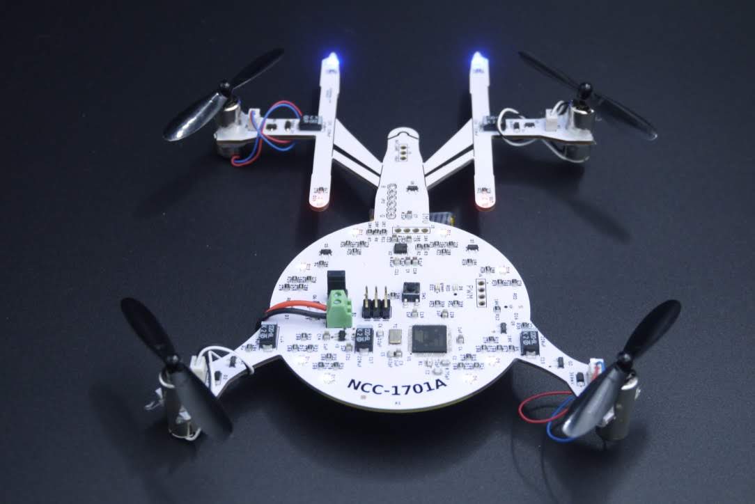
At the same time as this we were to start thinking about our final quadcopter design. The only real constraint was that it had to fit on a certain size PCB (the maximum allowed at a certain price point by the PCB manufacturers JLCPCB). We decided to make a Star Trek inspired Starship Enterprise shaped quadcopter. All credit to Max for doing the design in Fusion360 and importing it to Eagle to be our outline. He designed it so that the centre of mass and the centre of the 4 arms were the same place. That meant that we didn’t need to compensate in any way in software for any imbalance.
We decided on a number of different LEDs that we wanted to add. We decided to make a ring of RGB LEDs so that we could add different effects around the rim of the Enterprise. We also added two bright throughhole red LEDs that were to simulate blasters. We did have a power budget so we were constrained in how many LEDs to add.
PCB Layout
We then had to decide on how to layout the components that we had specified. We wanted to try a two sided board layout where we placed components on both sides of the PCB, this would have reduced the density and complexity of routing but would require an extra step in assembly and more chance of errors during that process. We would have had to reflow one side with a high temperature solder and then a second reflow on the second side with lower temperature solder. This is possible but we didn’t have access to the right temperature solders and decided that the risks involved were not worth the benefit of reduced layout complexity. We did have plenty of space to lay out our components so it was not necessary.
There were a few components that we had to place and route manually to ensure certain characteristics, the main one being the balun and antenna routing. The traces needed to be exactly symmetrical to ensure that the signals stayed in phase which is particularly important for antenna signalling.
We laid out the planes for ground, 5V for the motors and 3V3 for the logic and then ran Eagle’s autorouting tool. This didn’t route every route perfectly so we did some reviews and manual checking and fixing after that.
We had a peer review session with another group to catch any last issues before sending it off for manufacture.
The Remote and dummy drone
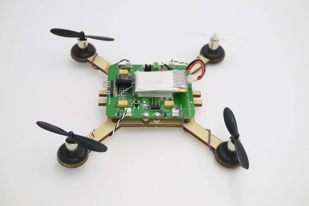
We needed a remote in order to control the to be constructed drone and we also needed a stand-in drone to start writing software to control it. The boards took a couple of weeks to be produced and shipped to us so to make sure we didn’t waste any time our professor provided us with very simple drone boards and wooden frames to use as standins - videos/picture here.
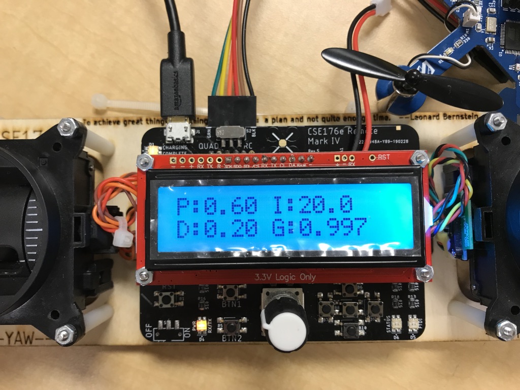
The remotes also needed to be constructed from the board, frame and associated components.
These were great test beds for us to get started writing the firmware
Firmware
One of the most challenging aspects of the project was the interaction of software and hardware. We used several libraries from adafruit for communication via 2.4ghz radio (wifi) between the remote and the drone. But that was about where the external software ended, we wrote the software that interpreted the inputs from the joysticks, calibrated them, sent them to the quadcopter, interpreted position from the onboard IMU and managed the thrust from the motors based on all the above.
I did most of the work on the remote programming, we had several screens for carrying out different functions, calibrating the joysticks. Max and I worked for several days on IMU calibration issues.
Everything was in C++ which I hadn’t used before but other than a few odd syntax issues it was fine.
Max did the most work on the quads software including the calibration code which he knocked together very quickly to try and solve the issues we were having with bizarre readings coming out of the IMU when the motors were running.
We found a few things crucial to making it run correctly, having the main loop run at exactly the right rate (so the software polling the IMU was in phase with the IMU measurement and production rate) also the voltages that the system were running on seemed to make an outsize difference, one battery would work fine but another brand - fully charged - and it would wobble all over the place, completely unstable. When we swapped the jumper cable for a short jumper tab it improved performance notably.
Conclusion
We were lucky and happy to have the only stable quadcopter in the class - okay there may have been some hard work in there too. I have written a couple of blog posts to dive in more detail about some of the specific problems we faced and how we overcame them.
The final product